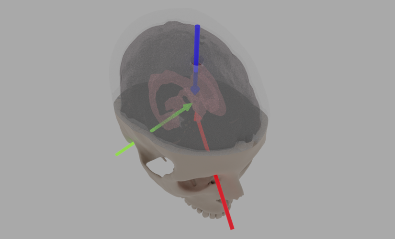
Alignment and outside references when performing the ventricular surgery. The blue arrow is where the catheter enters, and the aim is to insert it to where the green (estimated through the ear canal) and red (from where the eyebrow connects to the nose bone) meet.
Photo and screenshots taken by Mario Romero, Alessandro Iop, and Ingemar Markström.
3D Modeling for simulated ventricular surgery
InfraVis User
Alessandro Iop
InfraVis Application Expert
Ingemar Markström (KTH)
InfraVis Node Coordinator
Björn Thuresson (KTH)
Tools & Skills
Blender, 3D Modeling
Keywords
Material design, 3D Modeling
Background
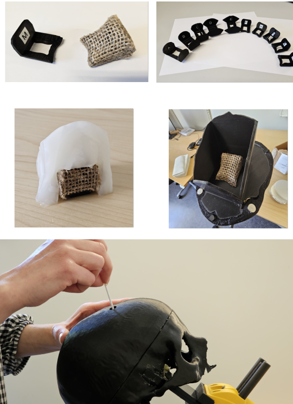
When fluid builds up inside of the brain and exceeds healthy levels, there exists a particularly sensitive surgery procedure in which a hole is drilled into the skull, followed by inserting a catheter into the hole and brain, aiming for the lower part of the ventricles. When punctured, the steel part of the catheter is pulled, leaving the tube as a drainage channel for the ventricle fluid to escape through. It is a technically difficult procedure, and training is done on artificial skulls and brains. This is where this project comes in.
The main center piece of this particular training setup revolves around a 3D printed/molded artificial Jello brain sample located inside a plastic skull. The goal of the exercise is to insert the catheter far, but absolutely not too far, into the Jello brain. The Jello is similar to a human brain in viscosity and resistance, providing the artificial sensation of actually practicing the procedure on a real brain. The InfraVis contribution to the project consisted of assisting in the creation, remodeling and assembling of various 3D printed items critical to the setup of the experiments in the project, as well as teaching and transferring knowledge for future development by the PI himself.
Modeling
The high-resolution 3D model of the skull was provided by the PI, of which one 3D print already existed. The original model consisted of the skull top and bottom as separate pieces, but some heavy mesh rework was needed since the cut was far from clean with many overlapping/missing triangles. After cleanup, the work started on the various versions of scaffolds. The scaffolds’ job is to provide support and holding the Jello brain sample in place. In that way, only a small part of the brain needs to be molded and used, vastly saving on material and handling. The brain Jello sample needs to be kept cold and wet, so the less material used, the better. Creating a tight cutout negative of the bottom inside of the skull model as well as fitting it snuggly to the inside of the top half of the skull was necessary since the Jello brain would risk ending up elsewhere. After deciding on a design that we deemed functional, the scaffold as well as the presumed brain sample (inside the scaffold) was sent to a specialist in Delft who molds the brain samples, which arrived the weeks after.
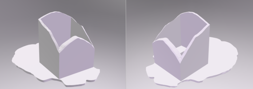
The drilled hole in the top of the skull has to be placed In relation to the placement of the scaffold. After consultation with the PI and the surgeons at Karolinska Hospital another part of the project was the placement of the optimal hole location for educational and practice purposes. After all was done a completely new skull was 3D printed.
Mo-cap accessories
Next on the agenda was a continuation in the hunt for a solution to one of the main hard problems in this whole research: 4D Tracking of the skull and the catheter. Work done prior to the InfraVis project involvement focused on real-time tracking in VR using Steam VR trackers, but the weight of the trackers at the time proved much too heavy and obstructive, severely reducing the immersive experience of performing simulated surgery in a VR environment. The aim was to create tracker trees for the skull and catheter, now with the idea of instead using mo-cap and process the collected data in post. The weight of the new small clip-on tree for the catheter was only a few grams, proved strong enough to survive testing. If it was broken, the print time for a new tree was half hours. The question was of course whether or not the precision would be good enough to track the catheter tip all the way from the other end of it. Because of the tree tracking balls results showed that yes, it can, but it does not take into consideration the bending of the catheter in the hands of the surgeon. With some caveats the more important factor is the insertion depth, so the tradeoff was acceptable with regards to tip aim.
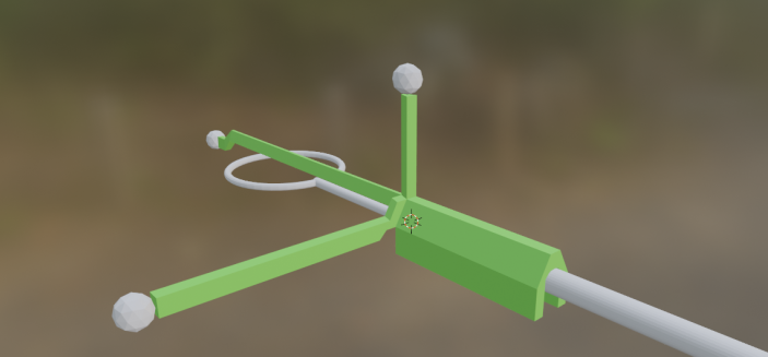
The tracking of the skull was done in the same way, but this tree was designed to be mounted out of the way of the surgeons’ hands. It was decided to have it mounted on the skull for reproducibility as well as minimized calibration once in the mo-cap studio, since it was always positioned in the exact same spot. It did not have to be pretty, but one key concept in a good mo-cap tree is to have non-repeating structures, saving huge amounts of time during the post process when mapping the tracked balls to items, cleaning up the tracking data and finally recreating the 4D movements.
We decided to print a completely new skull where the holes in the top were already taken out, embedding the tree in the forehead and making sure the scaffold would fit perfectly inside. The summary of this chapter consists of modelling in Blender, some kilo of PLA 3D printer material and many iteratively improved scaffolds and inserts, still holding up and being used to this day.
The canopy
This project mainly concerns the creation of a canopy placed inside the scaffold at the bottom where the catheter would enter the ventricles. The purpose of the canopy was to investigate and artificially simulate the sensation of breaking through the ventricle tissue wall by introducing a replaceable and similar-feeling material under tension, emulating the popping experienced by surgeons during the insertion of the catheter.
Although small, the conflicting requirements on the canopy were quite significant: Durability and reparability for repeated trials and tests, and realistic enough to resemble the actual real-world surgery. The investigatory work included materials for the membrane, and trying out multiple ways of mounting, minimizing the occurrence of bumping into the plastic frame during insertion.
The InfraVis involvement throughout this task was low-intensive over a long period of time. Apart from an intensive brainstorming startup, the PI took it on himself to further develop the first versions modelled, resulting in more than ten various versions of the whole design. The materials ended up as loosely woven natural fiber/hemp as the membrane, tucked over a standard PLA 3D print. It gave enough of a vertical punch through sensation, more than durable enough for multiple tests, and if unfortunately broken; a new one could be printed within an hour and used together with a new piece of cloth.
The PI is more than capable of independently improving the current designs as well as creating new props for his research. One core principle is to help the PI to help themself, and sometimes that involves a bit more time spent teaching in the short run, but quickly paying off in both time spent overall, quality and motivation.
One final note is on the choice of software used, namely the open-source 3D modelling program Blender. One approach could have been to do everything in a dedicated CAD program, because of the emphasis on measurements and geometry being highly correct. The perfect compromise came in the PI being quite proficient in Blender, and Blenders’ “good enough” Boolean operator tools. Blender emulates basic CAD functionality, and “basic” proved well good enough this time around. And, when some nice-looking images are later needed, I would rather have Blender produce them.